P Point Functions
Create and position point geometry using coordinates, intersections, tangencies, angular positioning, and geometric relationships.
Coordinate Point
Creates a point at specified X and Y coordinates. The foundation of all geometry construction.
Circle Centre Point
Creates a point at the exact centre of an existing circle — useful for referencing circular features.
Line / Circle Intersection
Creates a point at the intersection of a line and circle. Direction selectors (XL, XS, YL, YS) choose the correct solution.
Tangent Point — Circle/Circle
Creates a point at the tangent location between two circles.
Delta Offset Point
Creates a new point by applying X and Y offsets (dX, dY) to an existing reference point.
L Line Functions
Create and modify straight-line geometry using points, angles, parallel relationships, perpendicular relationships, and tangencies.
Line Through Two Points
Creates a line passing through two existing point references.
Parallel Line
Creates a line parallel to an existing line at a specified offset distance. Direction selectors determine which side.
Perpendicular Line
Creates a line perpendicular to an existing line through a specified point.
Tangent to Two Circles
Creates a line tangent to two circles simultaneously — common for profile construction.
C / A Circles & Arcs
Create circular geometry, arcs, fillets, tangent features, and other curved entities with full transient preview support.
Circle by Centre & Radius
Creates a circle at a specified centre point with a given radius.
Tangent Circle
Creates a circle tangent to existing geometry — lines, circles, or arcs.
Fillet Arc
Creates a fillet arc of specified radius between two intersecting geometry entities.
Geometry Trim
Trims lines, circles, and arcs to defined boundaries — essential for clean profile construction.
CAM Machining Functions
Define machining features, toolpaths, and generate CNC data for 3-axis milling operations directly from your 2D geometry.
Toolpath Generation
Generate machining toolpaths from 2D geometry profiles for CNC 3-axis milling operations.
Machining Depth Control
Define Z-axis depths and machining levels for each feature in the CNC program.
Tool & Cutter Data
Define cutter dimensions, tool numbers, and machining parameters for each operation.
Data Verification
Review and verify all machining parameters, depths, and toolpaths before generating the CNC program.
UCS Coordinate System & Editing
Work relative to translated or rotated coordinate systems, and edit existing geometry with full preview support.
Set Translation (UCS)
Temporarily shift the working coordinate origin to a new position without modifying existing geometry.
Set Rotation (UCS)
Temporarily rotate the working coordinate system to create geometry relative to an angled datum.
Mirror Geometry
Mirror selected geometry about a defined axis or line.
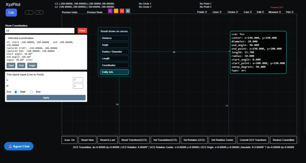
Geometry Information Display
View detailed entity data — coordinates, radius, start/end angles, arc sweep — for any selected geometry.
M Measure Functions
Click directly on geometry entities to measure and inspect. XyzPilot's measurement tools provide instant, accurate data — distances, angles, radii, lengths, coordinates, and full entity information.
Distance
Measure the distance between two selected geometry entities — points, lines, circles, or arcs.
Angle
Measure the angle between two selected lines or geometry entities.
Radius / Diameter
Measure the radius or diameter of a selected circle or arc entity.
Length
Measure the length of a selected line or arc entity.
Coordinates
Display the exact X and Y coordinates of a selected point or entity position.
Entity Info
Click any entity to display full property data — type, centre, radius, start/end points, start/end angles, sweep degrees, length, and clockwise/counter-clockwise direction.
DXF File Import
XyzPilot can import DXF files from any CAD system. The importer is a strict 2D primitive extractor — it reads valid DXF files using ezdxf and converts supported geometry directly into XyzPilot's internal geometry envelope. All DXF versions from AutoCAD R12 through 2021+ are supported.
Point Import
DXF POINT entities are converted directly to XyzPilot point geometry {x, y, z}.
Line Import
DXF LINE entities are converted to XyzPilot line geometry {x1, y1, x2, y2}.
Circle Import
DXF CIRCLE entities are converted to XyzPilot circle geometry {cx, cy, r}.
Arc Import
DXF ARC entities are converted into XyzPilot trimmed arcs, preserving centre, radius, start angle, and end angle.
Lightweight Polyline
LWPOLYLINE entities are decomposed into individual line and arc segments. Bulge values are converted to arc geometry automatically.
Polyline Import
POLYLINE entities are decomposed into lines and arcs. Bulge segments are extracted and converted to trimmed arc geometry.
Geometry Bounds
After import, XyzPilot automatically computes geometry bounds — min/max X, min/max Y, width, and height — for display and CAM setup.
DXF Version Support
Supports AutoCAD R12, R2000, R2004, R2007, R2010, R2013, R2018, and 2021+. Compatible with AutoCAD, Fusion 360, SolidWorks, Onshape, FreeCAD, Rhino, and any DXF-exporting CAD system.